81 lines
3.6 KiB
Markdown
81 lines
3.6 KiB
Markdown
|
|
# DQz11N1G
|
||
|
|
|
||
|
|
|
||
|
|
|
||
|
|
Firmware for a DIY controller replacement for one of the ortholinear contoured
|
||
|
|
keyboards manufactured by [PCD Maltron Ltd](https://www.maltron.com)
|
||
|
|
|
||
|
|
This work here in no way officially associated with PCD Maltron Ltd and comes
|
||
|
|
with NO WARRANTY. Modifying your Maltron keyboard as described below will
|
||
|
|
certainly void your warranty and may cause damage to your keyboard. Proceed
|
||
|
|
at your own risk!
|
||
|
|
|
||
|
|
* maintainer: [David Kuehling](https://github.com/dvdkhlng/qmk_firmware_dqz11n1g)
|
||
|
|
* Hardware Supported: Maltron DQz11N1G with a replacement controller board
|
||
|
|
assembled as described below. The work here is based on a german version
|
||
|
|
of the keyboard: DQz11N1G-DE. I assume, but don't know for sure, that
|
||
|
|
minor or no changes at all are required to make this work on different
|
||
|
|
language versions of the keyboard.
|
||
|
|
* Hardware Availability:
|
||
|
|
* [PCD Maltron Ltd](https://www.maltron.com), for the original keyboard
|
||
|
|
* 1x [Arduino Pro Micro](https://www.sparkfun.com/products/12640)
|
||
|
|
* 3x [SN74HC165](https://www.ti.com/product/SN74HC165)
|
||
|
|
* 1x DIL connector 2 rows a 17 pins.
|
||
|
|
* 19x pull-down resistors (10k Ohm),
|
||
|
|
* 4 LED current limiting resistors (not sure about the correct resistance,
|
||
|
|
using 470 Ohm here)
|
||
|
|
|
||
|
|
Make example for this keyboard (after setting up your build environment):
|
||
|
|
|
||
|
|
make handwired/dqz11n1g:default
|
||
|
|
|
||
|
|
## In Detail
|
||
|
|
|
||
|
|
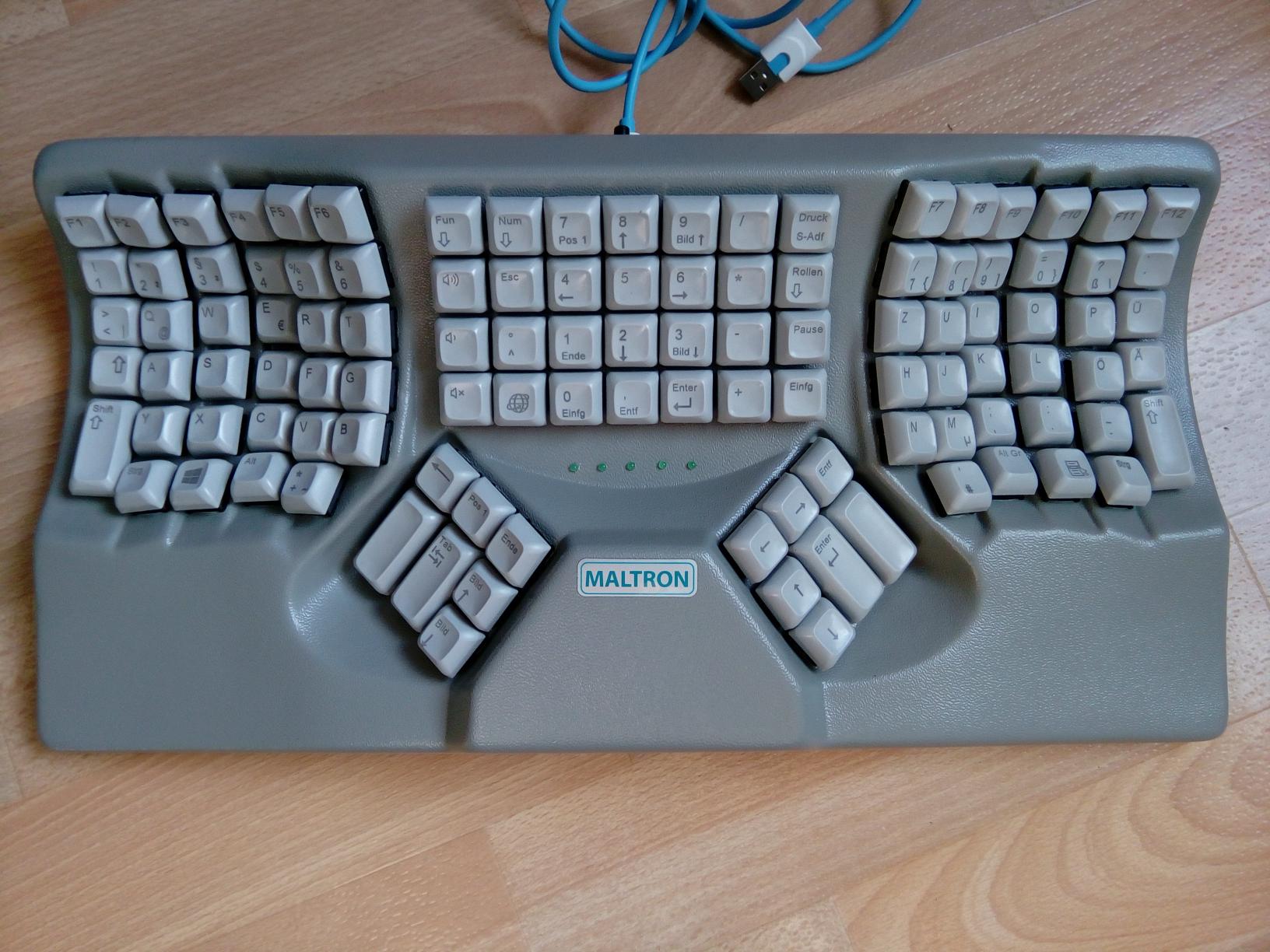
[PCD Maltron Ltd](https://www.maltron.com) manufacturs ergonomic keyboards
|
||
|
|
that appear to be hand-wired internally. For the Maltron DQz11N1G-DE
|
||
|
|
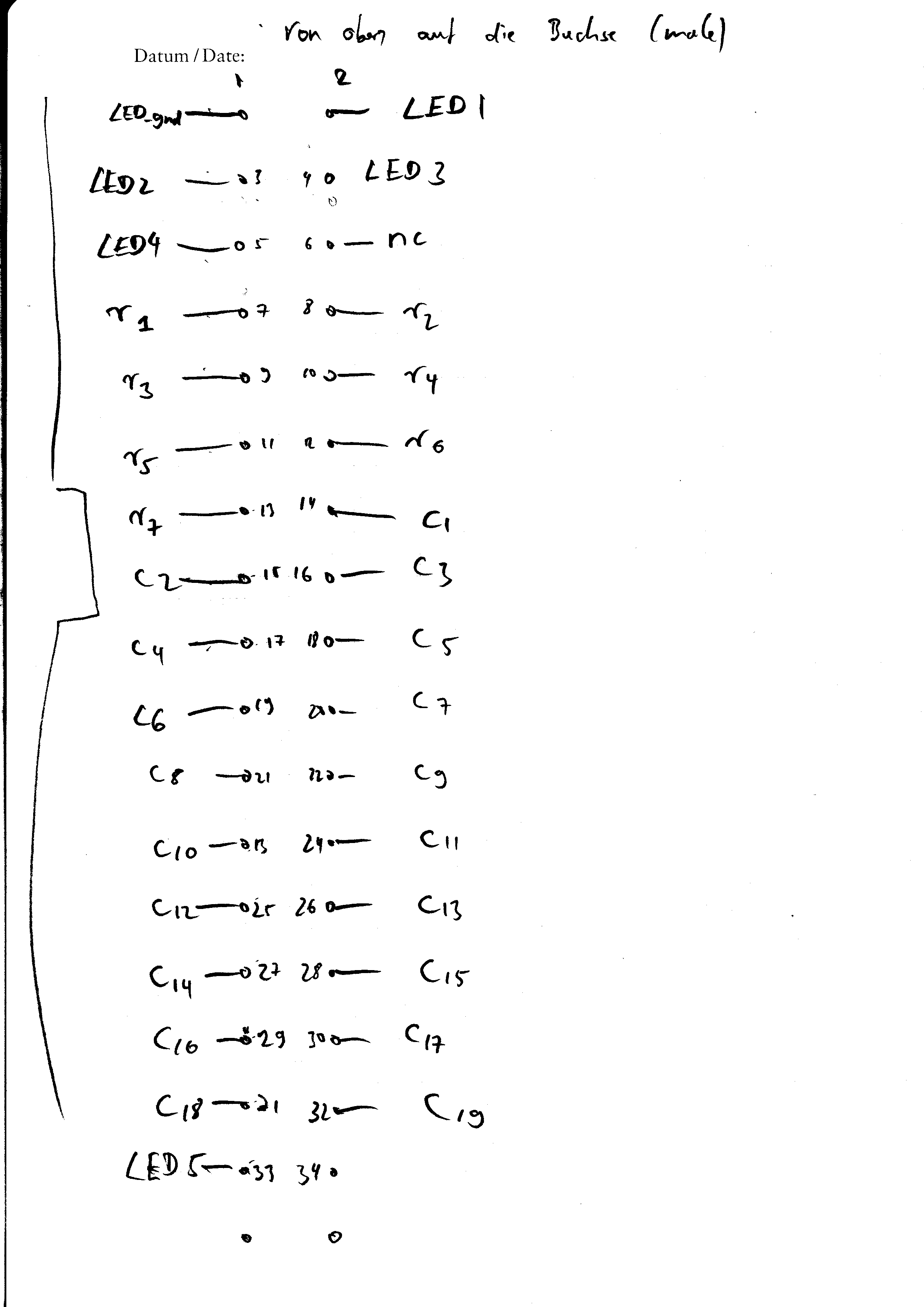
keyboard that I happen to own, the keyboard matrix is wired to a 34-pin DIL
|
||
|
|
connector. This makes it rather easy to replace the proprietary
|
||
|
|
controller-board with a self-made board based on the QMK firmware.
|
||
|
|
|
||
|
|
I don't really like the default layout of my Maltron DQz11N1G-DE keyboard,
|
||
|
|
and modding it to work with QMK allows me to adapt it to my needs. It
|
||
|
|
especially allows for the two space keys to assume different roles, thereby
|
||
|
|
creating an additional easily reachable thumb-key.
|
||
|
|
|
||
|
|
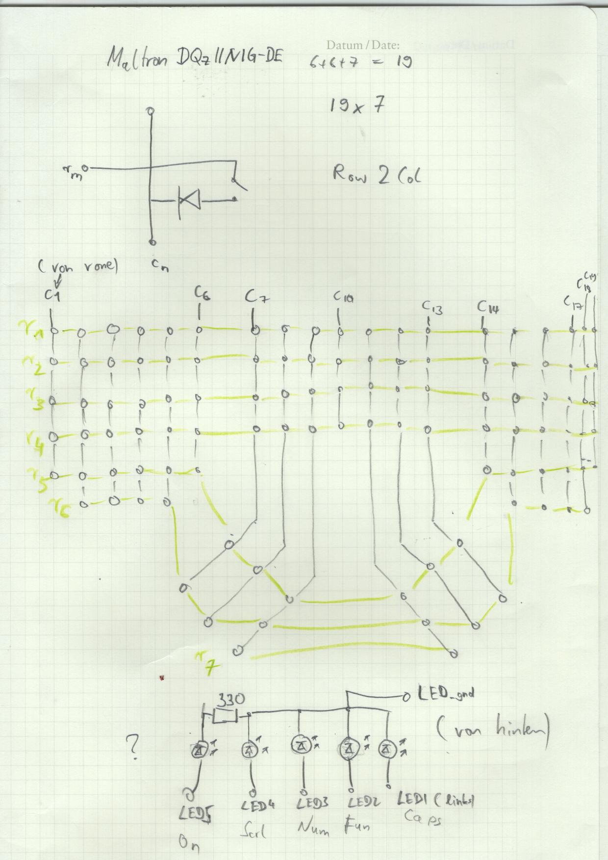
### Internal Details of Keyboard Matrix and DIL Connector
|
||
|
|
|
||
|
|
|
||
|
|
|
||
|
|
|
||
|
|
|
||
|
|
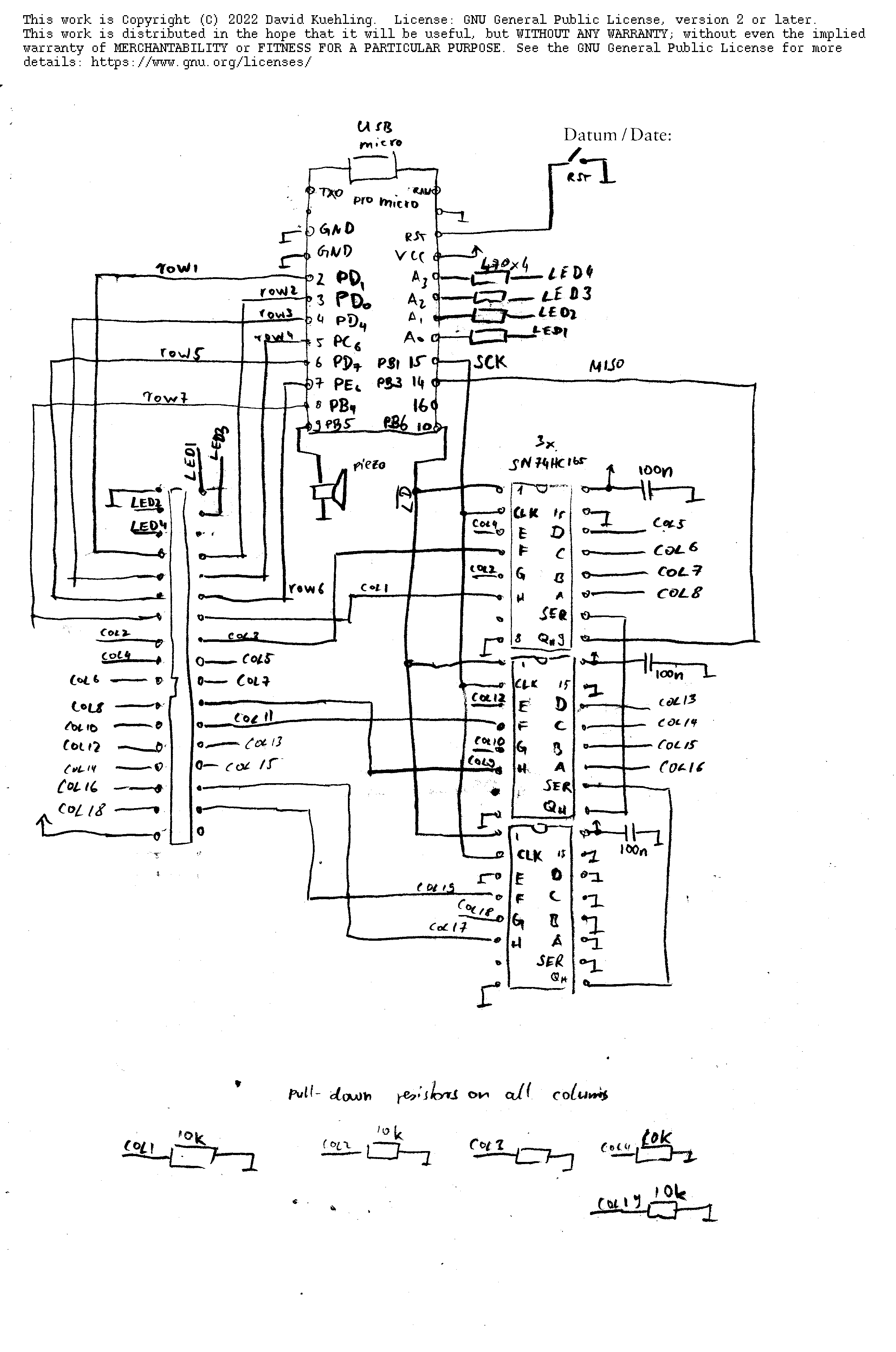
### Replacement Keyboard Controller Board
|
||
|
|
|
||
|
|
Due to supply chain problems, I decided to base this on an
|
||
|
|
Arduino-compatible [Pro Micro](https://www.sparkfun.com/products/12640)
|
||
|
|
board which is still easy to source.
|
||
|
|
|
||
|
|
Unfortunately pin-count of the DQz11N1G-DE's keyboard matrix is way beyond
|
||
|
|
the Pro Micro's available I/O pin count. I'm using three 8-bit
|
||
|
|
shift-registers ([SN74HC165](https://www.ti.com/product/SN74HC165) ) to
|
||
|
|
connect the 19 colums of the keyboard matrix for readout. Due to diode
|
||
|
|
direction in DQz11N1G-DE we also need 19 pull-down resistors one for each of
|
||
|
|
the utilized shift-register inputs.
|
||
|
|
|
||
|
|
This is a design sketch of the replacement board this is based on. Note how
|
||
|
|
we need a custom matrix.c source file to deal with the shift register based
|
||
|
|
keyboard readout.
|
||
|
|
|
||
|
|
|
||
|
|
|
||
|
|
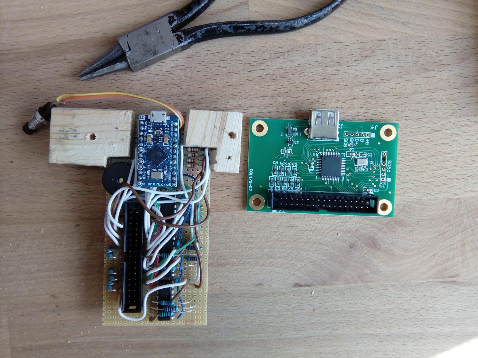
This is how the assembled controller board looks like, on the right side you
|
||
|
|
see the original PIC-based controller the keyboard ships with.
|
||
|
|
|
||
|
|
|
||
|
|
|
||
|
|
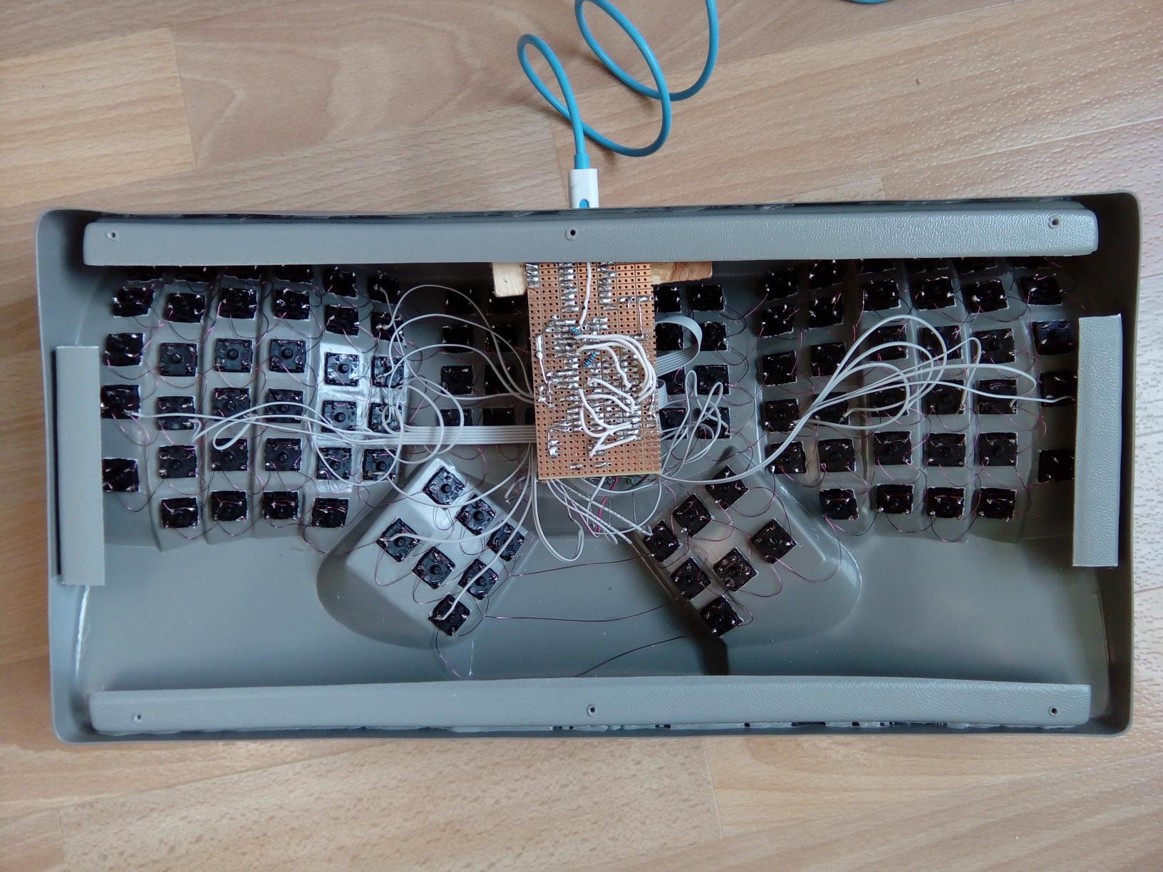
Inside of the keyboard after installing the new controller board:
|
||
|
|
|
||
|
|
|
||
|
|
|
||
|
|
(Not visible in the photo: I drilled hole into the keyboard above the USB
|
||
|
|
connector for a reset switch to simplify flashing controller firmware)
|